


USBprog - An open source all purpose tool (AVR ISP, ARM7/ARM9, AT89,JTAG, RS232, IO) |
| New bootloader available! No problems under windows! |
usbprog adapter - The kit ist available for 22 EUR and the New hardware version 3.0 is now available. Read more! AVR ISP 2 clone OpenOCD Adapter |
 |
 |
| usbprog Online (Program for Linux and Windows) |

1. What is usbprog?
usbprog is a free programming adapter. You can easily install different firmware versions from an "online pool" over USB. The adapter can be used for programming and debugging AVR and ARM processors, as USB to RS232 converter, as JTAG interface or as simple I/O interface (5 lines).
2. Who needs usbprog?
Hardware and software developers who work with Windows, Linux and other operating systems.
3. What is so special about the concept of usbprog?
Given time, there will be a growing pool of firmware versions. If you have to work with a new module you will ideally find the matching firmware to program or connect to this new module in the online pool.
If there is no matching firmware for the required module you shouldn't hastily buy a far too expensive adapter, but ask if it paid to write a new firmware for usbprog and thus to invest in the firmware pool. Often it is done quite quickly, because you can enhance existing software tools. Like in the case of the AVR ISP 2 clone that can be used with every application that supports the original adapter of Atmel, or the adapter for the OpenOCD, a product developed within 2 to 3 days.
As the whole project is an open source project, it should be interesting for a long time!
If you have any questions, information or criticism feel free to write an email to sauter@ixbat.de
Abstract of the FIRMWARE pool:
The software on the adapter can be directly changed by the consisting USB connection via an easy to use update mechanism. This works easily with a graphical programm, available for Windows and Linux.
The hardware can be ordered as a kit including PCB in our ==> online shop
Therefore the schemes are available in our downloads section (schematic circuit diagram, PCB layout, etc.).
WebTaxi Architecture
Service Based Architecture
A Web Server running will control WebTaxi service. The web server will interact with the external off-the-shelf services to get the job done. The main idea here is to minimize the development effort and use existing web services. Message communication with web services will be using Extended Markup Language (XML) definition of these services.
The following services will be used to implement the complete system:
-
Mapping Service: This service expects the source and destination addresses in a standard XML format. It responds back with an XML document containing the exact route and the estimated time of the journey.
-
Mobile Messaging Service: This service allows message communication with PDAs with cell phone capabilities. The service expects a message in the XML format. The XML message should contain the phone number of the destination device. The service provides device transparency by sending the XML document over the air interface used by the device. In a similar fashion XML messages from these devices can be delivered to the service originator. This service also supports multicasting to a select group of mobile devices. This feature is used by the WebTaxi server to locate the taxi that can service the request.
-
Credit Card Billing Service: This service is used to charge the customers credit card for the taxi service.
-
Bank Account Service: This service is used to deposit the money into the taxi driver’s account.
The interactions between the WebTaxi server and the web services is shown in the figure below:

WebTaxi Server Overview
The Web Taxi server forms the front end of the WebTaxi system. The customer interacts with the WebTaxi website housed on the WebTaxi server. The server goes through the following steps to service a Taxi Request:
-
Customer places a Taxi Request on the WebTaxi server
-
Server uses the Mapping Service to locate the start point and end point of the journey.
-
The server then uses the Mobile Messaging service to broadcast the request for a Taxi.
-
Response to the request is received from the Mobile Messaging Service.
-
WebTaxi server further interacts with the Taxi PDA devices to pinpoint the taxi that will serve the customer. All these interactions will use the mobile messaging service.
-
When the taxi service is completed, the server will bill the customer’s credit card using the Credit Card Service.
-
Money will be credited into the Taxi Drivers account using the Bank Account Service.
Taxi PDA Overview
Every taxi driver has a PDA with a built in cellular phone. This PDA acts as the front end for the taxi driver. The Taxi PDA goes through the following steps to handle a Taxi service:
-
Taxi PDA receives a service request from the WebTaxi Server (WTS). This request is a broadcast from the server. The request specifies the maximum time a taxi can take to qualify for this service.
-
The handling of the request depends on the current state of the Taxi:
-
Free Taxi: If the taxi is currently free, the PDA gets the estimate of the time to serve from the mapping service by specifying the source as current taxi location and the destination as the service start time.
-
Busy Taxi: If the taxi is serving a customer, the time to serve estimate is obtained by asking the mapping service for the time taken in going from the current location to the start of service point via the end point of the current service.
-
Busy and Booked Taxi: If a taxi is currently busy and it has a future service assigned to it, the taxi will ignore the request.
-
If the time is below the maximum time specified by the WTS, Taxi PDA then reports the start of service time to the WebTaxi Server. (It may be noted here that a Taxi PDA would typically go through several such transaction before it gets "chosen" for the service. The taxi driver will have no knowledge of these transactions)
-
If WTS likes the reply, it will query the driver for service acceptance.
-
If the driver accepts the service, Taxi PDA will inform WTS.
-
In a similar fashion, Taxi PDA will inform the WTS about "ready for service", "start of service" and "end of service".
Click the link to view the WebTaxiDesign
Robotics/Embedded Systems Part-I

Introduction
This article is Part I of a series of articles which is an attempt to introduce the reader into the world of embedded systems and their applications in the industry. I have decided to divide the topic into several parts that will be presented gradually as I complete them. The objective of the series will be a general discussion of embedded systems and what they are. In the process, I will also show how to assemble a basic robot using a robotics kit provided by Parallax which will be controlled through the BASIC Stamp II microcontroller. Towards the end of the series, I will start using the Microsoft Robotics Studio to illustrate some of the features available through the new IDE provided by Microsoft, if time permits.
So what is an embedded system? In general terms, an embedded system is any device that includes a programmable computer for a specific task. Sometimes it is also said that, an embedded system is nearly any computing system other than a desktop computer. Embedded systems are found everywhere these days! Your cell phone, digital camera, portable video games, calculators, digital watches, and etc… the list can go on for a really long time. This gives you an idea of the broad application base of embedded systems.
Background/Reference
Understanding of computer architecture and microcontrollers is a plus for this series of articles. I will be discussing system design and theoretical concepts of microprocessor. Also some basic electronics knowledge would be helpful once we get into circuit design for the robot. All this will be provided and I will try to make it a good learning experience.
Characteristics of Embedded Applications
Embedded systems have several common characteristics that distinguish them from other computing systems: Single Function, Tightly Constrained, and Reactive to Real Time.
- Single Function: An embedded system usually executes a specific program repeatedly.
- Tightly Constrained: All computing systems have constraints on design metrics, but these constraints can be extremely tight on embedded systems.
- Reactive and Real Time: must continually react to changes in the system's environment and must compute certain results in real time without delay.
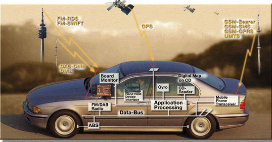
An example of a real time embedded system is the computing systems in most of modern day cars. For example, BMW uses highly sensitive and sophisticated embedded systems to make the ride a better and safer experience for the driver. The 5 series, for example, makes several million calculations per second and uses this information to make proper adjustments to the critical components of the vehicle. Let's take a closer look at some of these components for a better understanding.
ABS (Antilock Brake System) and (ASC+T) Automatic Stability Control + Traction
An antilock brake system reduces skidding by pumping the brakes. An automatic stability and control system intervenes with the engine during maneuvering to improve the car's stability. These systems actively control critical systems of the car.
With ABS, sensors measure the speed at which the wheels are turning. If this decreases rapidly, the electronic steering system reports blocking danger. The pressure of the hydraulics is reduced immediately and then raised to just under the blocking threshold. The process can be repeated several times per second, and you can notice it by the pulsation on the brake pedal.
To improve ABS, BMW places a sensor on every single wheel. The advantage of 4 sensors is the higher regulation precision. By sensing 4 individual rpm's of the wheels, the braking power on the rear axle can be adjusted with a great deal more sensitivity.
BMW's four wheel-speed sensors are in constant contact with all four wheels, providing greater accuracy than systems that use just three sensors. Each sensor carries accurate feedback from a specific wheel independently. A three-sensor system provides an average wheel-speed figure for rear wheels.
Automatic Stability Control + Traction is a suspension control system that reduces engine output, until the vehicle can move or acceleration can take place, without the wheels spinning. This happens regardless of how the driver is using the accelerator. If the reduction in acceleration is not enough, each drive wheel is braked individually until both wheels have optimum traction. Braking is under control of the BMW pioneered Anti-lock Braking System (ABS) system.
Intelligent regulation systems prevent the vehicle from swerving when accelerating on a loose surface, insuring that directional stability is reliably maintained.
- If a wheel threatens to spin, the wheel brake is applied or else the system intervenes to regulate the engine management accordingly. Only so much throttle is applied to insure lateral stability, even if the accelerator is fully depressed.
- An integrated engine drag torque regulation system stops the drive wheels from blocking if the driver suddenly removes his foot from the accelerator.
- The system can be switched off if you desire.
The ABS and ASC+T systems must clearly communicate because the ASC+T interacts with the brake system. Since the ABS was introduced several years earlier than the ASC+T, it was important to be able to interface ASC+T with the existing ABS module, as well as other existing embedded modules. The engine and control management units include the electronically controlled throttle, digital engine management, and electronic transmission control. The ASC+T control unit has two microprocessors, one of which concentrates on logic-relevant components, and the other on performance specific components.
Now that we have seen an example of a real world embedded system and its usefulness, let us concentrate on the technology itself.
Processor Technology
Processor technology relates to the architecture of the computation engine used to implement a system's desired functionality.
General Purpose Processors: The designer of a general purpose processor or a microprocessor builds a programmable device that is suitable for a variety of applications to maximize the devices sold.
Single Purpose Processor: A single purpose processor is a digital circuit designed to execute exactly one program.
Application Specific Processor: An application specific instruction set processor (ASIP) can serve as a compromise between the general purpose processor and the single purpose processor. As ASIP is a programmable processor optimized for a particular class of applications having common characteristics, such as embedded control, digital-signal processing, or telecommunications.
Using a general purpose processor in an embedded system may result in several design benefits. Flexibility is high because changing functionality requires changing only the program. Time to market would be low, and unit cost would be low in small quantities compared to designing your own processors. Performance may not be as great for some more computation intensive applications.
Using a single purpose processor in an embedded system results in several design metric benefits. Performance may be fast, size and power may be small, and unit cost may be low for large quantities.
Using an ASIP in an embedded system can provide the benefit of flexibility while still achieving good performance, power and size. Microcontrollers and digital signal processors are two well known types of ASIPs that have been used for several decades. A microcontroller is a microprocessor that has been optimized for embedded control applications.
Digital signal processors (DSPs) are another common type of ASIP. A DSP is a microprocessor designed to perform common operations on digital signals, which are the digital encoding of analog signals likes video and audio.
We will be more concentrating on general purpose processors.
General Purpose Processors
A general purpose processor is a programmable digital system intended to solve computational problems in a large variety of applications.

The same processor can be used to solve computational problems in applications as diverse as communication, automotive, and industrial embedded systems.
Basic Architecture
A general purpose processor consists of a data path and a control unit tightly linked with a memory.
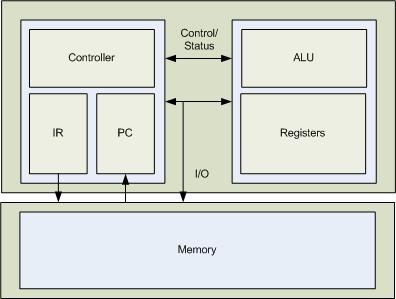
Datapath
The datapath consists of the circuitry for transforming data from and for storing temporary data. It consists of an arithmetic logic unit (ALU) capable of transforming data through operations such as addition, subtraction, logical AND, logical OR, inverting and shifting.
The datapath also contains registers capable of storing temporary data. Processors are typically distinguished by their size, and we usually measure the size of the processor as the bit width of the datapaths components. Common processor sizes include, 4-bit, 8-bit, 16-bit, 32-bit and 64-bit. The processor which we will be using for our robot construction is a 16-bit general purpose processor.
In some cases a particular processor may have different sizes among its registers, ALU, internal bus or external bus. For example, a processor may have a 16-bit internal bus, ALU and registers, but have old 8-bits of external but to reduce the number of pins on the processor's IC.
We will discuss the processor in more detail in the second part of the article.
Control Unit
The control unit consists of circuitry for retrieving program instructions and for moving data to, from and through the datapath according to those instructions.
For each instruction the controller typically sequences through several stages, such as fetching the instruction from memory, decoding it, fetching operands, executing the instruction in the datapath, and storing the results. Each stage may consists of one or more clock cycles. A clock cycle is usually the longest time required for data to travel from one register to another.
Memory
While registers server a processor's short-term storage requirements, memory server the processor's medium and long-term information-storage requirements. We can classify storage information as either program or data.
Program information consists of the sequence of instruction that cause the processor to carry out the desired system functionality. Data information requests the values being input, output and transformed by the program.
Points of Interest
This introduction is only a scratch on the surface of computer architecture. It covers the basic ideas and gives a footing for the reader for the remaining parts of the article series. There are a lot of good books on computer architecture available that you can study to get a deeper understanding of the subject. I will list some of the books that I have used and think that are worthwhile for reading and reference.
- Computer Organization, by Carl Hamacher, Zvonko Vranesic, Safwat Zaky
- Computer Architecture: A Minimalist Perspective (The International Series in Engineering and Computer Science) (Hardcover), by William F. Gilreath, Phillip A. Laplante
There are of course more books on the subject which you might want to consider. Keep in mind the objective of this article is not computer design and architecture, but how to use the concepts to implement a simple embedded system; we will use a robot to demonstrate the concepts.
Robotics/Embedded systems Part-II
Introduction
This article is Part II of a series of articles attempting to introduce the reader to the world of embedded systems and their applications in the industry. In this article we will concentrate more on the BASIC Stamp II microcontroller and how it will be used in our robotics project. If you have not read Robotics/Embedded Systems Part I please take some time to read it to get an insight into the possibilities of robotics and embedded systems.
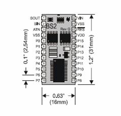
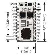
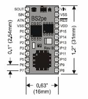
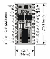
The figure above, illustrates the BASIC Stamp II microcontroller. In the following sections we will get into the details of the microcontroller and get an overview of its architecture, the Input and Output (I/O) pins present, and the instruction set for the microcontroller.
Background/Reference
Understanding of computer architecture and microcontrollers is a plus for this series of articles. I will be discussing system design and theoretical concepts of microprocessor. Also some basic electronics knowledge would be helpful once we get into circuit design for the robot.
Brief History of the BASIC Stamp Microcontroller
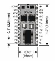
BASIC Stamp microcontrollers have been in use by engineers since they were introduced in 1992. Since their introduction, the BASIC Stamp line of microcontrollers has evolved into six models and many physical package types. We will be using the BASIC Stamp 2e microcontroller for constructing and controlling our robot.
The following table lists the model comparison for the BASIC Stamp II microcontrollers. Of course since the architecture of some of the more advanced microcontrollers are different, the instruction set is also different and handled differently internally.
| Microcontroller | Description |
|
|
|
|
|
|
|
|
|
|
|
|
|
|
|
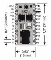

We will be using BASIC Stamp 2e as the brains for our robot.
Features of the BASIC Stamp Microcontrollers
BASIC Stamp II microcontrollers are designed for use in a wide array of applications. Many projects that require an embedded system with some level of intelligence can use the BASIC Stamp modules as the controller. Each BASIC Stamp microcontroller comes with a BASIC Interpreter chip, internal memory (RAM and EEPROM), a 5-volt regulator, a number of general purpose I/O pins (TTL-level, 0-5 volts), and a set of build in commands for math and I/O pin operations. They are capable of running a few thousand instructions per second and are programmed with a simplified, but customized form of the BASIC programming language, called PBASIC. We will cover some of the PBASIC commands in this article. More will be covered as we start building the robot.
BASIC Stamp II Architecture - Memory Organization
The BASIC Stamp II microcontroller has two kinds of memory, RAM (for variables used by the program) and EEPROM (for storing the program itself). EEPROM may also be used to store long term data.
The BASIC Stamp II model has 32 bytes of Variable RAM space. The first six bytes are reserved for input, output, and direction control of the I/O pins. The remaining 26 bytes are available for general purpose use as variables. It has an extra INS, OUTS and DIRS registers for a total of 38 bytes of variable RAM. These are shadow registers that are switched in and out of the memory map with the AUXIO, MAINIO, and IOTERM commands. The following table will show the arrangement of the RAM space:
| WORD Name | BYTE Names | NIBBLE Names | BIT Names | Special Notes |
| INS | INL, INH | INA, INB, INC, IND | IN0-IN7, IN8-IN15 | Input pins |
| OUTS | OUTL, OUTH | OUTA, OUTB, OUTC, OUTD | OUT0-OUT7, OUT8-OUT15 | Output pins |
| DIRS | DIRL, DIRH | DIRA, DIRB, DIRC, DIRD | DIR0-DIR7, DIR8-DIR15 | I/O pin direction control |
| W0 | B0, B1 | |||
| W1 | B2, B3 | |||
| W2 | B4, B5 | |||
| W3 | B6, B7 | |||
| W4 | B8, B9 | |||
| W5 | B10, B11 | |||
| W6 | B12, B13 | |||
| W7 | B14, B15 | |||
| W8 | B16, B17 | |||
| W9 | B18, B19 | |||
| W10 | B20, B21 | |||
| W11 | B22, B23 | |||
| W12 | B24, B25 |
The word variable INS is unique in that it is read only. The 16 bits of INS reflect the state of I/O pins P0 through P15. It may only be read, not written. OUTS contain the states of the 16 output latches. DIRS controls the direction (input or output) of each of the 16 I/O pins.
A 0 in a particular DIRS bit makes the corresponding pin in an input and a 1 makes the corresponding pin an output. For example, if bit 5 of DIRS is 0 and bit 6 is 1, then I/O pin 5 is an input and I/O pin 6 is an output. A pin that is an input can e controlled by circuitry outside the BASIC Stamp II microcontroller, and the microcontroller cannot change its state. A pin that is an output is set to the state indicated by the corresponding bit of the OUTS register.
When the BASIC Stamp II is powered up, or reset, all memory locations are cleared to 0, so all pins are inputs (DIRS = %0000000000000000). Also, if the PBASIC program sets all the I/O pins to outputs (DIRS = %1111111111111111), then they will initially output low, since the output latch (OUTS) is cleared to all zeros upon power up or reset.
In summary, DIRS determines whether a pin's state is set by external (input, 0 ) or by the state of OUTS (output, 1). INS always matches the actual state of the I/O pins, whether they are inputs or outputs. OUTS holds bits that will only appear on pins whose DIRS bits are set to output.
As stated previously, the BASIC Stamp II module's memory is organized into 16 word of 16 bits each. The first three words are used for I/O. The remaining 13 words are available for use as general purpose variables.
Defining Variables for BASIC Stamp II Microcontrollers with PBASIC
Before using variable(s) in a PBASIC program, they must be declared. The following is a sample of how to declare a variable for BASIC Stamp II microcontroller:
name VAR Size
where name is the identifier of the variable and Size indicates the number of bits of storage for the variable.
For the BASIC Stamp II microcontroller, the Size argument has four different choices:
-
Bit (1 bit)
-
Nib (nibble, 4 bits)
-
Byte (8 bits)
-
Word (16 bits)
Example of variable declarations:
| Sample Declaration | Range |
| myBit VAR BIT | Value can be 0 or 1 |
| myNib VAR NIB | Value can be 0 to 15 |
| myByte VAR BYTE | Value can be 0 to 255 |
| myWord VAR WORD | Value can be 0 to 65535 |
You can also define multipart variables called arrays. An array is a group of variables of the same size, and sharing a single identifier (variable name), but broken up into numbered cells, called elements. The syntax for defining an array in PBASIC is:
name VAR Size(n)
where Size(n) tells PBASIC how many elements the array to have. For example: myArray VAR BYTE(10) will create a 10-byte array. Another unique property of PBASIC is that you can refer to the 0th cell of the array by using just the array's name without an index value.
You can also use what is called an alias as an alternative name for an existing variable. For example:
myVar VAR BYTEmyAlias VAR myVar
This means that both names refer to the same physical memory location. The alias can also serve as a window into a portion of another variable. This can be done by the use of modifiers. For example:
myWord VAR WORDhighByte VAR myWord.HIGHBYTElowByte VAR myWord.LOWBYTE
where HIGHBYTE will represent the highest 8 bits and LOWBYTE will represent the lowest 8 bits. So if the value of myWord is 0001110111110000 then the HIGHBYTE will contain 00011101 and LOWBYTE will contain 11110000.
The BASIC Stamp II microcontroller also has an additional RAM called Scratch Pad RAM. The size is 64 bytes. The Scratch Pad RAM can only be accessed with the GET and PUT commands and cannot have variable names assigned to them. The highest locations in SPRAM (location 63) is special-purpose, read-only location that always contains special run time information. The following is a table of the SPRAM:
| Location | BS2 |
| 0 to 62 | General Purpose RAM |
| 63 | Bits 0-3: Active program slot number. |
We will cover more of the instruction for the BASIC Stamp II in the next article.
Points of Interest
In the last few years, there have been much interest and enthusiasm in the fields of robotics. This is due to the availability of cheaper and more advanced microcontrollers. There is however one more frontier which needs to be addressed before we can see more interesting and sophisticated application introduced into the market place. And that is having standards for the industry. I see Microsoft's announcement of their Robotics Studio as a step forward in this direction, and from the looks of it, the industry has welcomed the initiation warmly! This will lead to the same phenomenon which happened to the personal computer in the early days with the introduction of the IBM PC. I feel that in the next few years and specifically in the next decade there will be great achievements in the robotics field, and maybe we can realize some of the dreams we have had growing up come true. Walking, talking, and thinking robots that can benefit humanity in many aspects.
Robotics/Embedded Systems Part-III
Introduction
This is Part III of a series of articles whose goal is to introduce the reader to the world of embedded systems and their applications. In Robotics/Embedded Systems Part I, I covered the general idea of what embedded systems are. I gave examples of embedded system applications that can be found within your car today. I also briefly covered the different types of processor technologies that are available to you for your projects: General Purpose Processors, Single Purpose Processors and Application Specific Processors. In Robotics/Embedded Systems Part II, I covered a specific general-purpose processor made by Parallax. The BASIC Stamp II microprocessor family was covered in some length. I then picked the BASIC Stamp II e (BS2e) model and went over the memory architecture and some of the basic commands.
In Robotics/Embedded Systems Part III, I will actually be building the robot using the Basic Stamp II microcontroller. This article is more of an introduction to the basic concepts of a robot and how they can be practiced. So without further ado, I will begin Part III of the series.
Background
Understanding of computer architecture and microcontrollers is a plus for this series of articles. I will be discussing system design and theoretical concepts of microprocessors. Also, some basic electronics knowledge would be helpful once we get into circuit design for the robot.
Project Overview
I will be using BASIC Stamp II for building and programming some fundamental functionalities of a robot. The objective of this article series is to build the following four essential functionalities, i.e. logic and circuits within the robot.
- Sense the world around itself using the sensors.
- Make decisions based on what it senses.
- Control its motion based on the sensors and its decisions.
- Exchange information back to the user.
In the next section, I will discuss the assembly and testing of the hardware.
Assembling and Testing of the Robot
In order to successfully complete the project, the following hardware and software is needed for the design and implementation of the robot. The following table will list the hardware necessary.
| Hardware component | Quantity |
| BASIC Stamp 2 Microcontroller Module | 1 |
| Board of Education Rev C | 1 |
| 1 KΩ Resistor | 2 |
| 10 KΩ Resistor | 2 |
| 2 KΩ Resistor | 2 |
| 220 Ω Resistor | 8 |
| 470 Ω Resistor | 4 |
| 4.7 KΩ Resistor | 2 |
| 0.01 µF Capacitor | 2 |
| 0.1 µF Capacitor | 2 |
| Infrared LED | 2 |
| Red LED | 2 |
| Photo resistors (EG&G Vactec VT935G group B) | 2 |
| Infrared Receiver (Panasonic PNA4602M or equivalent) | 2 |
| LED Standoff for Infrared LED | 2 |
| LED Light Shield for Infrared LED | 2 |
| 3-Pin Header | 2 |
| Whisker Wire | 2 |
| #4 Screw-Size Nylon Washer | 2 |
| 7/8" 4-40 Pan-Head Screw, Phillips | 2 |
| ½" Spacer, Aluminum, #4 round | 2 |
| Jumper Wires (bag of 10) | 2 |
| Piezo Speaker | 1 |
| Boe-Bot Hardware Pack | 1 |
We also need to get the software to be able to program the BASIC Stamp II microcontroller, as well as a USB driver (if using USB) to be able to establish communication with the Board of Education Rev C. The following table lists the software components that are needed for this project.
| Software component |
| BASIC Stamp Editor 2.0 or Higher |
| FTDI USB VCP Drivers |
Connecting the Hardware
The first thing we need to do is place the BASIC Stamp II microcontroller into its proper place on the Board of Education. This can be achieved via the following steps:
- Set the 3-position switch on the Board of Education to position 0.
- Load batteries into the battery pack.
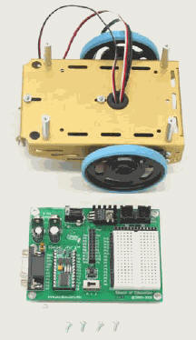
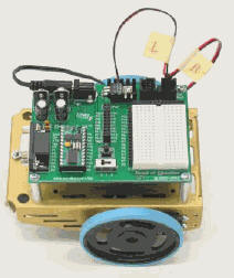
- Plug the BASIC Stamp II microcontroller into the Board of Education, inserting it into the socket as shown below:
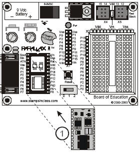
NOTE: Make sure that the pins are lined up properly before pushing the microcontroller into the socket.
Before we continue on, we should test and make sure that we are able to communicate with the BASIC Stamp II microcontroller. If you have not yet installed BASIC Stamp Editorand FTDI USB VCP Driver, now is the time to do so. I will not cover installation of the software in this article; it should be straightforward. Run the BASIC Stamp Editor. Under the main menu, select Run->Identify… and a window should appear indicating if the hardware was detected or not.
If you are able to connect to the hardware successfully, you can test the microcontroller with a simple program. We will basically ask the microcontroller to send a message to the PC it is connected to. Here is the listing of the program used for testing the microcontroller:
' BASIC Stamp send a text message to the PC
' {$STAMP BS@}
' {$PBASIC 2.5}

DEBUG "Hello, this is Ed the robot!"

END
We need to transfer the program to the microcontroller. To do this, select Run -> Run from the main menu. Alternatively, you can press Ctrl+R as a keyboard shortcut. A download window will appear briefly as the program is being transmitted from the PC to the microcontroller. Once the program has been transmitted, you will see the test message, "Hello, this is Ed the Robot!" on the debug window.
Explaining of the Test Program
The first two lines of the code are called compiler directives and every PBASIC program will have them at the beginning. The first directive is called the Stamp Directive and it tells the Editor that you will be downloading the program to a BASIC Stamp II microcontroller. The second directive is called the PBASIC Directive and it tells the Editor that we are using version 2.5of the PBASIC programming language.
The DEBUG command tells the BASIC Stamp microcontroller to send a message to the PC using the serial cable. The END command, puts the BASIC Stamp into low power mode when it's done running the program. At this point, the microcontroller waits either for a reset button to be pressed or a new program to be loaded into the memory.
Assembly of the Robot
You can download the full manual from Parallax that gives detailed instructions on how to construct the robot. Here, I am going to cover the assembly of the robot in a shorter and faster way. That is, I will not get into too many details!
Mounting Servos to the Chassis

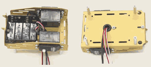
Mounting the Battery Pack
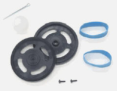
Mounting the Wheels
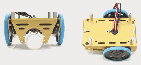
Attaching the Board to the Chassis
We need to test the servos after we have assembled the robot. This will help us make sure everything is working properly. To test the servos, we are going to use the following program, which will rotate the servos clockwise for 3 seconds and counterclockwise for 3 seconds.
' {$STAMP BS2}
' {$PBASIC 2.5}

DEBUG "Program Running!"

CounterVARWord

FOR counter = 1 to 122'Clockwise three seconds
  PULSOUT 12, 650
  PAUSE 20
NEXT

FOR counter = 1 to 40'Stop one second
  PULSOUT 12, 750
  PAUSE 20
NEXT

FOR counter = 1 to 122'Counterclockwise three seconds
  PULSOUT 12, 850
  PAUSE 20
NEXT
Controlling and Programming the Servos
Navigation is the main objective of any robotics project. The robot needs to be able to navigate in a given environment based on its sensors and the logic behind it. This is done through certain commands in the PBASIC language, which instruct the BASIC Stamp II microcontroller on how to control the direction, speed and duration of the servo motions.

The Parallax Continuous Rotation servos are the motors that will make the robot wheels turn. Controlling the servo motor's speed and direction involves a program that makes BASIC Stamp II send the message, over and over again. The message has to repeat itself around 50 times per second for the servo to maintain its speed and direction. Before moving forward, I will now describe some important commands that will be used for the purpose of controlling the servos. We will later discuss them in more detail.
The PAUSE command is used to tell the microcontroller to wait for a certain duration in milliseconds before executing the next command, i.e.: PAUSE 1000 will pause for 1 second. The DO and LOOP command is used to tell the microcontroller to repeat the commands in between the DO and LOOP code block until a condition is met, or forever, depending on the need of the application. For example, the following code will send a message every second.
DO
DEBUG "Hello!", CR
PAUSE 1000
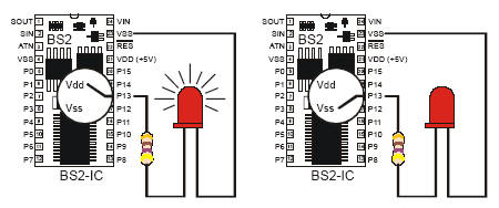
LOOP The HIGH and LOW command can be used to make BASIC Stamp alternate between Vdd and Vss. The pin argument is a number between 0 and 15 that indicates which I/O pin to connect to Vdd or Vss, i.e.: HIGH 0 will tell the microcontroller to set I/O pin 0 to Vdd. Similarly, LOW 0 will tell the microcontroller to set I/O pin 0 to Vss. The following figure illustrates the HIGH and LOW command:
DO
  HIGH 13
  PAUSE 1000
  LOW 13
LOOP
The code above will make the LED connected to pin 13 turn on and off every second.
Controlling the Servos
The high and low signals sent to BASIC Stamp II to send the servo motors must last for very precise amounts of time. This is because it is used by servos as instructions about where to turn. For this, we need more a precise command for controlling time duration.
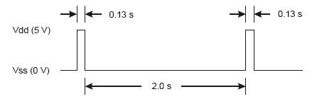
The PULSOUT command can deliver high signals for precise amounts of time. Time is measured in units of two millionths of a second. For instance, you can send a signal to P13 (pin 13) that turns on the LED for 2µs, i.e.: PULSOUT 13, 1. PULSOUT 13, 65000 is the equivalent of running a high signal for 0.13 seconds. The following is a timing diagram for the high signal:
Connecting the Servos to the Board of Education
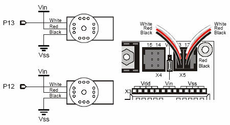
The first thing we need to do is connect the servos to the board. We will be using P13 and P12 of the microcontroller to send signals to the servos. The following schematic illustrates how this is done:
The next step is to actually center the servos. We need to write a program that sends the servos a signal, instructing them to stay still. The program for this signal will be a PULSOUT command and a PAUSE command inside a DO...LOOP. The following is a timing diagram for centering the servos:
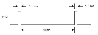
From the timing diagram we can tell that for the PAUSE command we need a duration of 20ms, which is going to be PAUSE 20. For the 1.5ms we need to use the PULSOUT command such as: PULSOUT 12, 750. How to figure out the PULSOUT command's durations? 1.5 ms is 0.0015 s. Remember that whatever number is in the PULSOUT command's duration argument must be multiplied by 2 µs, i.e. 0.000002 s.
Duration argument = Pulse duration / 2 µs, i.e.: 0.0015s/0.000002s = 7500.
If the servo is already centered, it will not turn. If it is not centered, you will need to adjust the servo by slowly using the screw driver in the potentiometer access hole.
Testing the Servos
The Parallax Continuous Rotation servo turns full speed clockwise when you send it 1.3 ms pulses. Full speed ranges from 50 to 60 RPM.
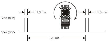
The following program will perform what we need:
' {$STAMP BS2}
' {$PBASIC 2.5}

DEBUG "Program Running!"

DO
  PULSOUT 13, 650
  PAUSE 20
LOOP
A duration of 850 will send 1.7 ms pulses to the servo and will make the servo turn full speed counterclockwise.
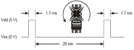
' {$STAMP BS2}
' {$PBASIC 2.5}

DEBUG "Program Running!"

DO
  PULSOUT 13, 850
  PAUSE 20
LOOP
Controlling Servo Runtime
Here is an example of a FOR...NEXT loop that will make the servo turn for a few seconds:
FOR counter = 1 TO 100
  PULSOUT 13, 850
  PAUSE 20
NEXT
Each time through the loop, the PULSOUT command lasts for 1.7 ms. The PAUSE command lasts for 20 ms and it takes around 1.3 ms for the loop to execute. So, one time through the loop is = 1.7 ms + 20 ms + 1.3 ms = 23.0 ms. Since the loop executes 100 times, the time is 23 ms x 100 = 2.30 s.
With the basics in place, we can now start programming our robot to navigate in its surrounding environment. We can create the following subroutines that will help us coordinate the movement of the robot with the sensors. Here, I will list the four basic movements: Forward, Backward, Left and Right:
Forward:
FOR counter = 1 to 64
  PULSOUT 13, 850
  PULSOUT 12, 650
  PAUSE 20
NEXT
RETURN

Backward:
FOR counter = 1 to 64
  PULSOUT 13, 650
  PULSOUT 12, 850
  PAUSE 20
NEXT
RETURN

Left:
FOR counter = 1 to 24
  PULSOUT 13, 650
  PULSOUT 12, 650
  PAUSE 20
NEXT
RETURN

Right:
FOR counter = 1 to 24
  PULSOUT 13, 850
  PULSOUT 12, 850
  PAUSE 20
NEXT
RETURN
You can also build complex maneuvers, but I will not cover those in this article.
Giving the Robot Some Sense
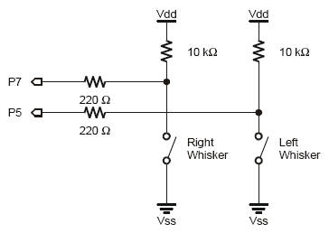
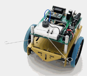
Whiskers give the robot the ability to sense the world around it through touch, much like the antennae on an ant or the whiskers on a cat. The whiskers can also be combined with other sensors to make the robot more intelligent. First, we need to assemble the whiskers based on the schematic:
The final look and feel of the robot after we have attached the whiskers may be:
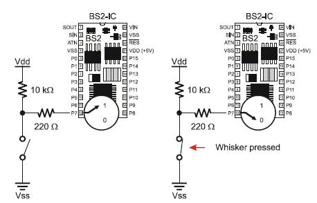
The next step is for us to program the BASIC Stamp II microcontroller to detect when a whisker is pressed. The I/O pins connected to each switch circuit monitor the voltage at the 10 kΩ pull-up resistor. When a given whisker is not pressed, the voltage at the I/O pin connected to that whisker is 5 V. When a whisker is pressed, the I/O line is shorted to ground (Vss), so the I/O line sees 0 V.
The following program is a test program that will report the state of the whiskers on the debug screen:
DEBUG "WHISKER STATE", CR,
  "LEFTRIGHT", CR,
  "========"

DO
  DEBUG CRSRXY, 0 , 3,
      "P5 = ", BIN IN5,
      "P7 = ", BIN IN7
  PAUSE 50
LOOP
Here you see two new commands, BIN and CRSRXY. The BIN command is a formatter that tells the Debug Terminal to display one binary digit, either 1 or 0. The CRSRXY command is a formatter that allows us to conveniently arrange information on the Debug Terminal. 0 and 3 indicate the column and row of the cursor on the terminal. I also attached an LED to the circuit. This way, we have a visual indicator of which whisker is being activated once the robot is not attached to the terminal. We will need to make the following addition to our circuit and also add a few extra lines of code to turn the LEDs on and off appropriately.

Add the following code to the program to make it work:
IF( IN7 = 0 ) THEN
  HIGH 1
ELSE
  LOW 1
ENDIF

IF( IN5 = 0 ) THEN
  HIGH 10
ELSE
  LOW 10
ENDIF
We can now write a program that will give the robot some intelligence when it collides with an object sensed by the whiskers. As soon as an object is detected, we would use the subroutines defined previously under the Navigation section of this article in order to perform the correct movement. I will outline the main section of the program here.
IF (IN5 = 0) AND (IN7 = 0) THEN
  GOSUB Back_Up ' Both whiskers detect obstacle,
  GOSUB Turn_Left ' back up & U-turn (left twice)
  GOSUB Turn_Left
ELSEIF (IN5 = 0) THEN ' Left whisker contacts
  GOSUB Back_Up ' Back up & turn right
  GOSUB Turn_Right
ELSEIF (IN7 = 0) THEN ' Right whisker contacts
  GOSUB Back_Up ' Back up & turn left
  GOSUB Turn_Left
ELSE ' Both whiskers 1, no contacts
  GOSUB Forward_Pulse ' Apply a forward pulse &
ENDIF ' check again
If both whiskers are pressed, a U-turn is executed. If the left whisker is pressed, then we will back up and make a right turn. If the right whisker is pressed, we will back up and make a left turn. The only thing this code does not cover is the occurrence of corners. For that, we need to write additional code.
The full source code for corner detection can be found in the following section. In brief, however: We have allocated two variables to store the old values of the whiskers. This will allow us to compare the whiskers to their previous values. If the robot then hits a wall four times in a short period, there is a counter that will call logic to back the robot up and make a 180 degree turn. It will then continue on its new path.
Source Listing for Whisker Navigation
' TestWhiskers.bs2
' Display what the I/O pins connected to the whiskers sense
' {$STAMP BS2}
' {$PBASIC 2.5}

DEBUG "Program Running!", CR
DEBUG "WHISKERSTATES", CR,
  "LeftRight", CR,
  "====== ======="

pulseCountVARByte'for..next loop
counterVARNib
old7VARBit
old5VARBit
FREQOUT 4, 2000, 3000'begining of the program
counter = 1
old7 = 0
old5 = 1

DO
  DEBUG CRSRXY, 0, 3,
      "P5 = ", BIN1 IN5,
      "P7 = ", BIN1 IN7
  PAUSE 50

  ' this condition is set for corner detection, if hit more then 4 times
  ' backup, turn 180 degrees and continue
  IF( IN7 <> IN5 ) THEN
      IF( old7 <> IN7 ) AND ( old5 <> IN5 ) THEN
          counter = counter + 1
          old7 = IN7
          old5 = IN5
          IF( counter > 4 ) THEN
              counter = 1
              GOSUB Back_up
              GOSUB Turn_Left
              GOSUB Turn_Left
          ENDIF
      ELSE
          counter = 1
      ENDIF
  ENDIF

  ' servo control based on whisker condition
  ' if both whiskers are activated, go back
  IF( IN5 = 0 ) AND ( IN7 = 0 ) THEN
      HIGH 1
      HIGH 10
      GOSUB Back_Up
      GOSUB Turn_Left
      GOSUB Turn_Left
  ELSEIF ( IN5 = 0 ) THEN ' right whisker activated
      HIGH 10
      GOSUB Back_Up
      GOSUB Turn_Right
  ELSEIF ( IN7 = 0 ) THEN' left whisker activated
      HIGH 1
      GOSUB Back_Up
      GOSUB Turn_Left
  ELSE ' nothing detected, go forward
      LOW 10
      LOW 1
      GOSUB Forward_Pulse
  ENDIF

  LOOP

  Navigation:
  ' my new implementation
  FOR counter = 1 TO pulseCount
      PULSOUT 12, pulseRight
      PULSOUT 13, pulseLeft
      PAUSE 20
  NEXT
  PAUSE 200
  RETURN

  Forward_Pulse: ' send a single forward pulse
  PULSOUT 12, 850
  PULSOUT 13, 650
  PAUSE 20
  RETURN

  Turn_Left:
  FOR pulseCount = 0 TO 20' left turn, about 90-degrees
      PULSOUT 12, 650
      PULSOUT 13, 650
      PAUSE 20
  NEXT
  RETURN

  Turn_Right:
  FOR pulseCount = 0 TO 20
      PULSOUT 12, 850
      PULSOUT 13, 850
      PAUSE 20
  NEXT
  RETURN

  Back_Up:
  FOR pulseCount = 0 TO 40
      PULSOUT 12, 650
      PULSOUT 13, 850
      PAUSE 20
  NEXT
  RETURN

END
